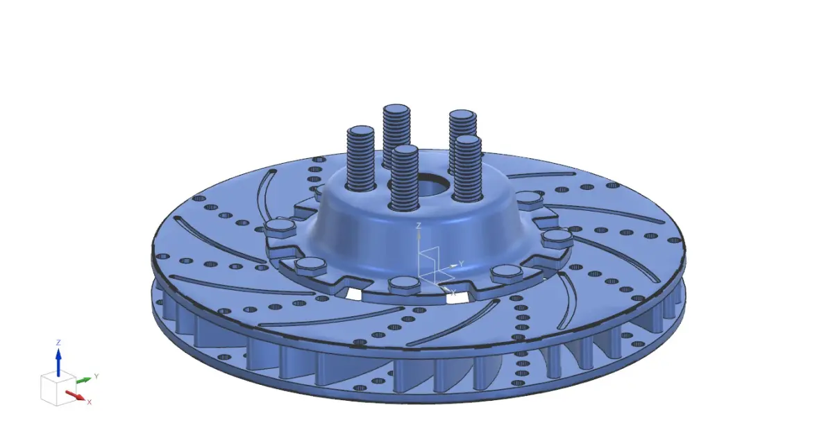
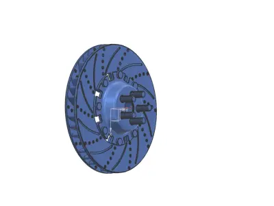
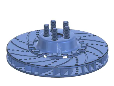
Creating a detailed 3D CAD model for a rotor disc brake assembly that includes components like the wheel hub assembly, rotor, and rotor hub involves designing and assembling these parts to ensure mechanical and functional integrity. Here’s a detailed breakdown of the process and description:
Components of the ModelWheel Hub Assembly:
Hub Body: Cylindrical or conical structure, typically made of cast iron, steel, or aluminum, designed to hold the wheel and other components.Bearing Housing: Integrated section to accommodate bearings for smooth rotation.Mounting Holes: Radial holes or slots for bolting the hub to the axle.ABS Ring (Optional): For vehicles equipped with an Anti-lock Braking System.Rotor (Disc):
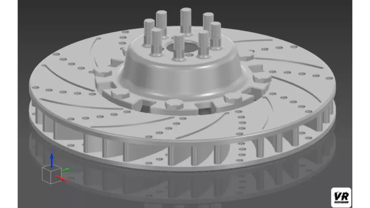
Rotor Disc Surface: Flat or vented structure, depending on the type (solid or ventilated disc), designed for efficient heat dissipation.Ventilation Channels (if applicable): Internal channels to improve airflow and cooling.Mounting Face: Circular flange area with bolt holes or slots that align with the rotor hub.Outer Edge: Precision-machined edge where brake pads contact the rotor.Rotor Hub:
Central Mounting Structure: Connects the rotor to the wheel hub assembly.Bolt Circle: A series of holes or threaded inserts matching the bolt pattern of the wheel hub.Reinforced Ribs (if applicable): For enhanced structural stability.Hub Face: Smooth, flat area for proper mating with the rotor.
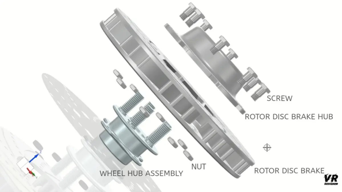
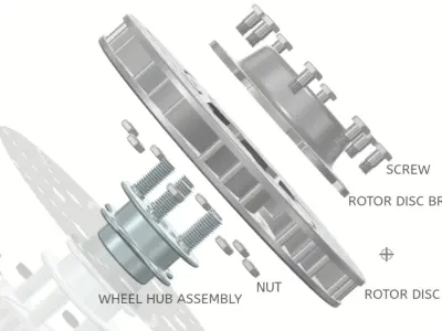
Assembly Description
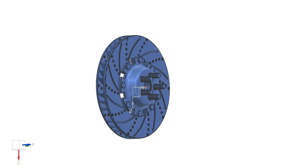
Wheel Hub to Rotor Hub Connection:The rotor hub is aligned and fastened to the wheel hub using high-strength bolts.Bearings in the hub assembly facilitate smooth rotation around the axle.Rotor Attachment:The rotor disc is mounted onto the rotor hub, aligning the bolt holes with the hub.Fasteners or press-fit mechanisms secure the rotor firmly to the hub.Alignment and Clearances:
The entire assembly is designed with precise tolerances to ensure concentricity, minimal wobble, and proper spacing between the rotor and brake calipers.Integration with Brake System:
The rotor disc is positioned such that the brake pads mounted in the calipers apply uniform pressure on the rotor surface during braking.3D CAD Modeling ConsiderationsMaterial Properties:
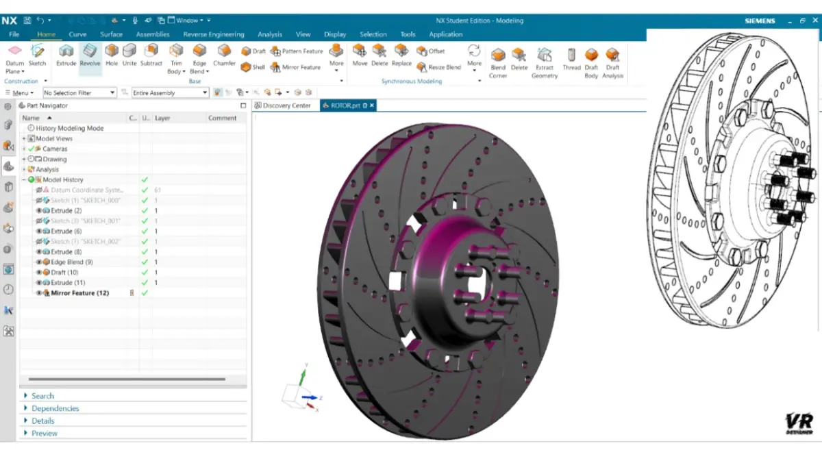
Assign appropriate materials (e.g., cast iron for the rotor, alloy steel for the hub) with accurate density, thermal, and mechanical properties.Geometric Details:
Include chamfers, fillets, and surface finishes where applicable.Ventilation designs, if any, should have proper flow paths.Assembled Constraints:
Ensure the parts are mated with realistic constraints such as fixed bolt connections, sliding fits, and rotational clearances.Simulation-Ready Design:
Prepare the model for finite element analysis (FEA) for stress, thermal, and dynamic simulations.
STL (Stereolithography, filesize: 5.77 MB), SLDPRT (SolidWorks, filesize: 277 KB), STP (STEP, filesize: 196 MB), OTHER (Other, filesize: 196 MB), FBX (Autodesk FBX, filesize: 11.1 MB)